Yes it is possible because the Rodecaster faders send MIDI. Bome MIDI Translator is a bit of an overkill for this single function, but I’m sure Steve will explain.
The crux is the hardware. Something has to switch on the LED when MIDI is received. You need some kind of interface for it. You can do this discretely with electronic components or with a microprocessor like Arduino, Teensy etc. Maybe you can find something ready-made for little money online.
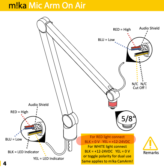
Well, in looking at the product, it looks like 3 wires come down from the Mic XLR connectors. These should go into the Rodecaster interface XLR. I suspect that the other 2 wires are from the Boom LED and we would need to know what the voltage and current requirements are to drive the LED. I suspect with the current in one direction it drives the red LED and in the other direction drives the white LED and when no current, of course the LED is off.
Yellowtec has an interface box that takes MIDI (or USB MIDI) in and I suspect uses the 5 pin connector to route up the arm of the boom. 3 of the pins for the Mic and 2 for the LED.
We would somehow need to design an interface that does similar. It could probably be done with a Arduino along with a relay hat. The relay would need a voltage source to drive the current if the Arduino doesn’t put out enough.
We could then program the Arduino to take a given MIDI command to convert that to drive the relay, hence the LED light color. I suspect the effort to design this solution would likely be more than the cost of the interface that Yellowtec sells.
Again, we would need to know the specs ‘current and voltage required’ of the light to determine the necessary parts needed for the relay module and power to drive the light.
Steve Caldwell
Bome Customer Care
Also available for paid consulting services: bome@sniz.biz
Yes, this should work but some sort of power would still be required to power the LED. The power source and possible a resister should go in series with the relay. We would still need to know the voltage and current requirements of the LED.
Steve Caldwell
Bome Customer Care
Also available for paid consulting services: bome@sniz.biz
I interpret: for red light, black cable on ground and yellow cable 12-24 Volts. Of course, there is a bit of manual work involved to get the two wires to the relay and to the power supply.
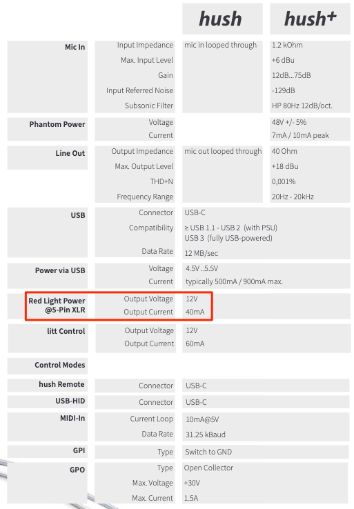
And the website shows specifications for the hush OnAir controller:
It delivers 12V 40mA to the LED.
This should mean that, without the hush controller, any standard 12V DC power supply can be used. I would ask the manufacturer to be sure.
The MIDI Solutions Relay has a programmable mode that closes the relay at an adjustable threshold. That is probably what is needed: Microphone fader up a little and red light goes on. And vice versa. I don’t know the relay box and if the programming tool runs on any computer.
If the Relay gets programmed, there is no reason for Bome MIDI Translator. If it doesn’t get programmed, there is another option where BMT would make sense: According to the description a standard function of the relay box is to CLOSE with one SysEx message and OPEN with another. I think this could be sent from BMT to the Relay box according to the (MIDI) fader position.
I doubt if you could get this solution for less than around 200 USD. Even with the MIDI Solutions product, you will still need an additional relay to switch current direction for both red and white LED.
Your options:
Buy the Yellowtec solution
Build it yourself.
Find someone to build it for you
For option 3 you can send me an email but I can tell you right now it would probably be over 200 USD. Maybe 30-40 USD in parts and another 150USD or more in labor for designing, building and programming.
The parts entailed would be:
Arduino UNO
Relay Shield
Power Supply
Wires and connectors
You would still need to purchase Bome MIDI Translator Pro to and would need 1 USB port available to power the Arduino. You would also need AC power for the power supply
Steve Caldwell
Bome Customer Care
Also available for paid consulting services: bome@sniz.biz
A micro switch built into the Rodecaster in such a way that the fader knob operates the lever of the switch in the end position. This is what I would prefer.
Appearance and efficiency of the construction depends on the technical skills and ideas of the builder. To drive the LED you need a small 12 V AC/DC power supply.
Otherwise, for the electronic solution, I think Steve’s offer is very good.
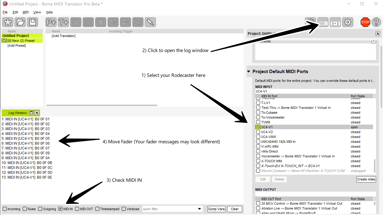
Here is a video showing how it can be done although I did not wire up the Yellowtec LED light. There is no sound.
The attached project file was used in this video.
To make it work it will require:
Arduino UNO or Mega (providing COM serial port functionality)
4 relay power shield
12 v power supply.
- To provide enough power to the Arduino to drive the relays
- To provide power to drive the LED
USB B to A cable (to connect Arduino to the Computer)
Wires between power supply and Relay Pins
USB cable (for MIDI between your MIDI controller and the Computer)
Wires between relay pins and LED.
Arduino Sketch for the relay shield purchased. Some relay modules use different pins.
(Sketch not included).
See me if interested. You can purchase hardware yourself or perhaps from me if I have it on hand.
The project file will not provide any useful action without the hardware or the Arduino Sketch that I created.
Also, when you sent email to me about this last November you said you had a Gator Frameworks boom arm and not Yellotec. It looks like the LED specs on this boom arm is quite different and if we wire it up like the Yellotec, it might blow out your LEDs
Steve Caldwell
Bome Customer Care
Also available for paid consulting services: bome@sniz.biz
Maybe it would just be better to get something like this? It would be lower cost in hardware and shipping and with some effort, I think I could figure out out to integrate it to use MIDI to activate it using their software API.
I wouldn’t spend any time on it without getting one first.
Steve Caldwell
Bome Customer Care
Also available for paid consulting services: bome@sniz.biz