Hi, please show the below example.
I use the first 6 faders to designate MSB and LSB values for red, green and blue.
Faders 1 and 2 hold red MSB and LSB
Faders 3 and 4 hold green MSB and LSB
Faders 5 and 6 hold blue MSB and LSB
I use global variable gb to hold the value of red, gc to hold the value of green and gd holds the value of blue.
In Preset 0 (Init) translator 2 (0.2). I set the initial values. I also set the target note (LED) number.
Translator 1.1 handles all of the fader manipulation and note values. I determine by fader which color to manipulate within the rules. Warning… they are likely too
complex for most users to understand at first but essentially I have to only update a portion of gb, gc, or gd since faders handle only 128 values and as I said earlier using MSB and LSB values together you get 16384.
As it turns out, it appears that only bit 0 of the MSB is used by the APC-MINI MK2 so essentially it recognizes only values of 0-255 with the MSB only being a 0 or 1. I didn’t find this out until after I completed and tested the project.
Translator 1.0 output is ‘Perform’ with the parameters of:
- Note Number
- Red Value
- Green Value
- Blue Value
Translator 1.1 takes these values and the splits them of to send a raw MIDI message using System Exclusive (SysEx)
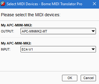
I use aliases as in my case I’m using named virtual ports instead of the actual device but I did test it with the actual device. You will need to point them to your actual controller.

You can learn more about aliases from this tutorial.
Also I set up my device management at the preset level.
For more information about device selection, see this tutorial.
If you open the MT Pro log window, you can see more information on what is happening.
apc-mini-mk2-color-control.bmtp (4.0 KB)
Happy learning!
Steve Caldwell
Bome Customer Care
Also available for paid consulting services: bome@sniz.biz
