Hello everybody ![]() ,
,
so here is my first version of a Novation V/A-Station remote panel for the Mackie C4 and i would like to share it.
Introduction:
The aim of the project is to truly showcase the power of a C4 and afterwards give Mackie C4 owners the possibility, to create things on their own. This midi controller is not well documented and if your software does not support it, you will be doomed, especially if you are on Mac OS. On release, there was once a software called ‘Total Commander’ that shipped with the Mackie C4, with which you could do remote panels easily, but this software has several downsides:
- It does not work anymore on any newer Mac OS (i think pre Intel-Macs where the last ones). No Rosetta-version.
- It does not support bi-directional work, so a panel cant react to program or parameter changes of the hardware for example.
- It also supports only one-time actions, so you cant use the push and turn function of a Vpot, only one of these per Vpot.
- It does not offer other functions like level metering, multiple Midi-Out etc.
- and last but not least, it only works with a PC of course.
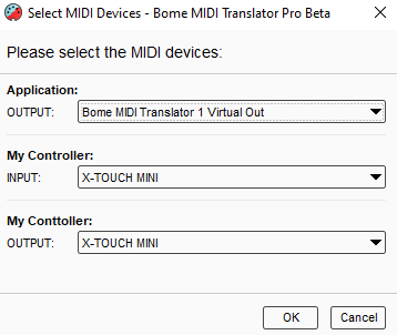
This midi controller is capable of so much more. With Bome MTP and this project, you will have full control over it, finally understand your midi-controller and are not limited to these restrictions.
In combination with a Bome Box, you dont even need a PC anymore. You can do a Live act, with your hardware only and still use remote panels (yes, plural ![]() ).
).
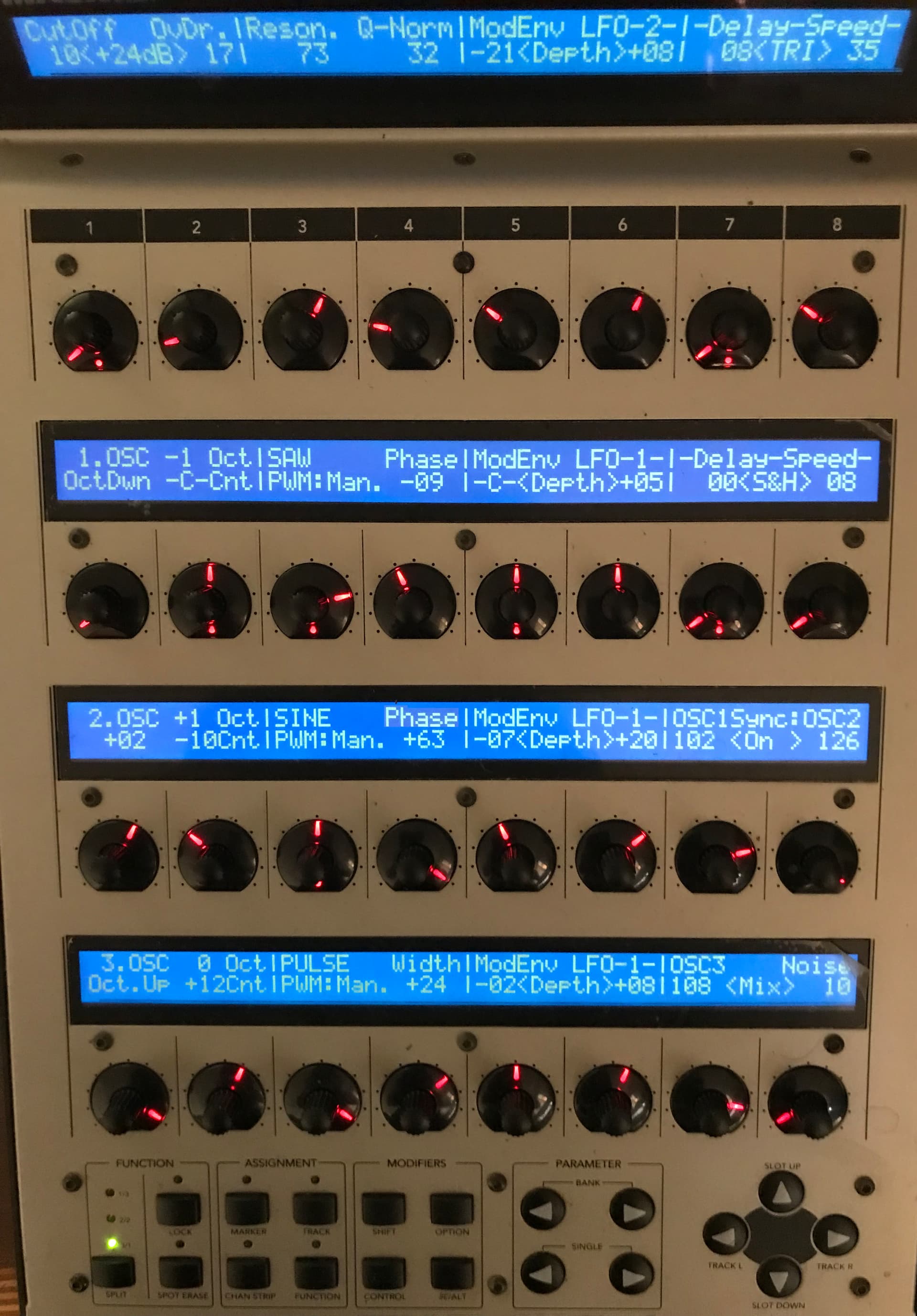
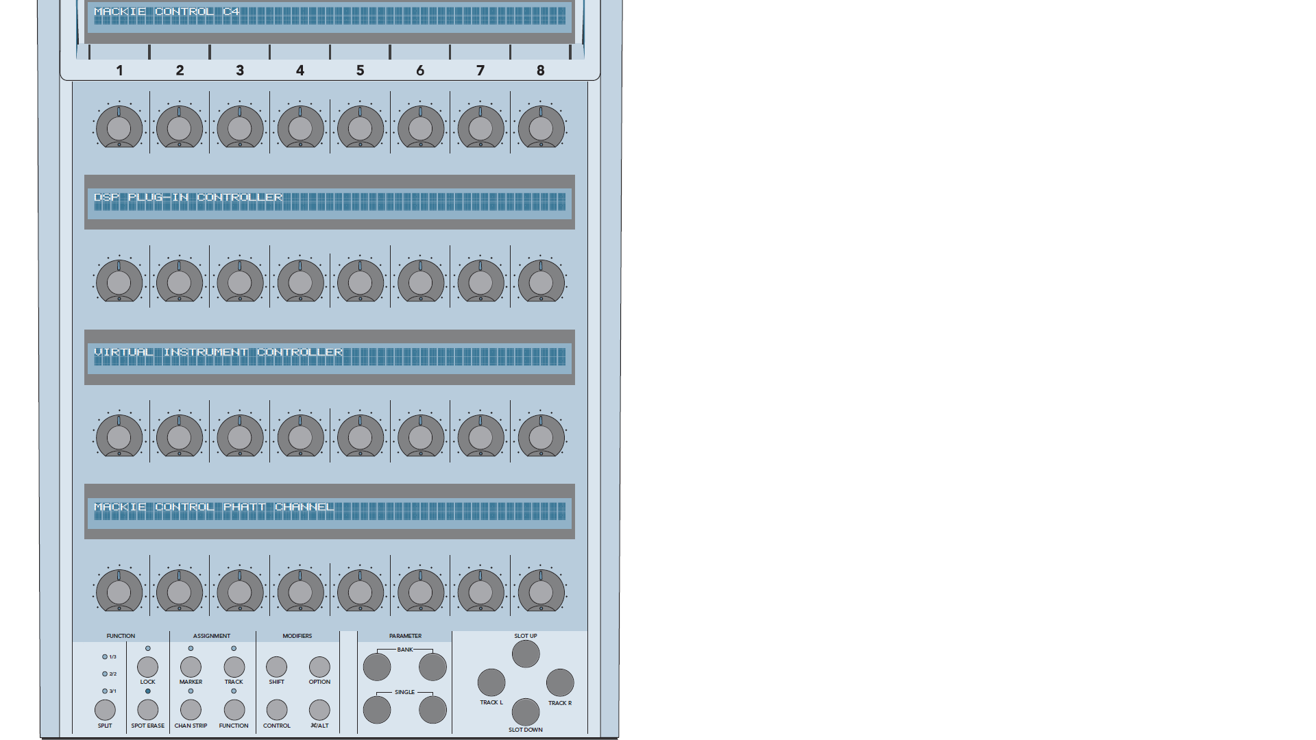
The 32 Vpots:
So lets start exploring how the Mackie C4 works and I will start with the Vpots first:
Vpots are endless rotary encoders that send relative ±values (starting from the value/parameter they want to control) and therefore they have not a limited operating value ‘range’. The limit here, is only the parameter range itself.
This has the advantage that they are ‘moving’ accurate in any operating range. Accurate, because the starting point for ‘moving’ is always the current parameter value. In comparison most (cheap) encoders that send absolute values, are only operating in a limited 0-127 value range, because this range is hardcoded into them. Also they are always ‘moving’ from the point you left them.
‘Yah, but is not that the same?’. No, it is not. For example, if there is a program/preset change, then there is mostly likely parameter value changes too. If you now ‘move’ a encoder that send absolute values, then the parameter value will ‘jump’ to the last point where this encoder was. This behaviour is not wanted and can be very annoying, depending what parameter is controlled. This is especially true, while editing/creating a patch or in a live gig scenario, where one track ends and you are using different sounds for the next track. Aaah, i love seeing that stickers and labels on a cheap, tiny midi-controller, leaving you confused and buzzed in a dark environment and all that live on stage ![]() . That makes your heart pumping
. That makes your heart pumping ![]() .
.
There where several attempts in the past, that tried to evade this problem and none of them are accurate. In a nutshell: relative encoders will jump to the parameter value and start moving from there, whereas absolute encoders will ‘force’ the parameter value to jump to them.
‘So we have 32 encoders with relative values sending, is this great then or not?’
Unfortunately in their default state, they are not sending ± 1 values and Mackie did not include a option to do so. If the soft or hardware has no option to support proper scaling of the sended values, you can not really use them in almost all situations, where you want them to use, mainly in the common 0-127 value range. Steinberg Cubase, for example, needed decades to give users a option for that. This is where MTP is needed, but lets get back to the topic.
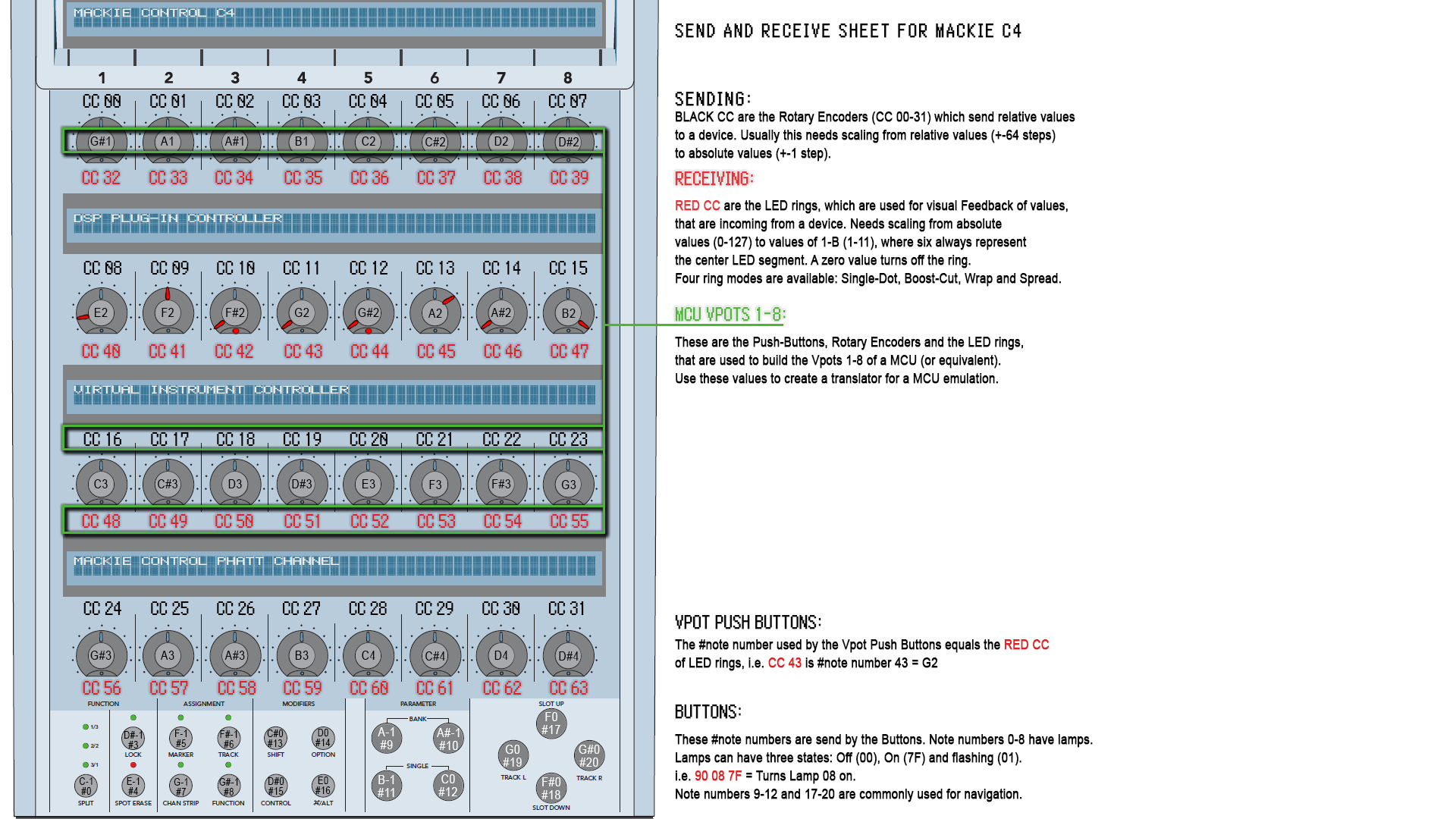
So the C4 has 32 Vpots, which send values with CC# 0-31 accordingly.
This is a bit awkward, because devs will tend to describe the Vpots in this way (using their CC# numbers). A normal person, does not think this way, as there is no Vpot 0 (in reality even the labeling of the hardware, does not follow this concept.) and so there is no Vpot 32, that he can find in comments of scripts either. I did my best to avoid this in my project, so that users can better follow the description and comments.
The 32 Vpots can also receive values from CC# 32-63 for their LED rings. Probably this was done to avoid infinite midi loops, that can cause hangs, crashes even blue screens. So as a thumb of rule, to adress the LED ring of a Vpot, you simply add 32 to the CC that a Vpot sends, to know the receiving CC number for the LED ring of that Vpot. Example: Vpot 1 will use CC#0 for sending and CC#32 for receiving values. I have attached style-sheets at the end of this post, that describe all CC# and note# numbers, that the Mackie C4 uses.
The LED rings can use four different ‘ring modes’, which i will decribe next. So in the example above we used Vpot 1, which can receives values on CC# 32. Depending on the value, you can use these ring modes described in this table:
*        Vpots 01-32 receiving:
*          CC# 32-63 + value             = ring mode:
*                CC# + value 00          = turns the LED ring Off.
*                CC# + value 01-11       = is used for Single LED ring mode.
*                CC# + value 16          = turns the LED ring Off.
*                CC# + value 17-27       = is used for Boost-Cut ring mode.
*                CC# + value 32          = turns the LED ring Off.
*                CC# + value 33-43       = is used for Wrap ring mode.
*                CC# + value 48          = turns the LED ring Off.
*                CC# + value 49-54       = is used for Spread ring mode.
*                CC# + value 55-63       = turns the LED ring Off
*                CC# + value 64          = turns on the pDot only
*                CC# + value 65-75       = turns on the pDot and is used in whole Single LED ring mode
*                CC# + value 80          = turns on the pDot only
*                CC# + value 81-91       = turns on the pDot and is used in whole Boost-Cut ring mode
*                CC# + value 96          = turns on the pDot only
*                CC# + value 97-107      = turns on the pDot and is used in whole Wrap ring mode.
*                CC# + value 112         = turns on the pDot only
*                CC# + value 113-118     = turns on the pDot and is used in whole Spread ring mode.
*                CC# + value 119-127     = turns on the pDot only
The four Ring Modes:
So in short, each ring mode uses eleven different values (or twelve if you add Off to it), to ‘move’ the LED segments (except for Spread that use only six). Each ring mode exists with or without a pDot. So for representing the common 0-127 value range with a LED ring, you will need to divide the range with eleven to have a evenly approximination showed of by the eleven LED segments of a ring (127/11). With Bome MTP you can create even a new ring mode, i.e. like this:
Tip: I recommend to use the pDot LED only for Vpots that will also use the push-function. This way a user can clearly see, what Vpot can also be pushed. Probably the reason why Mackie named that pDot. I also recommend to use the Single LED ring mode as much as possible. While it is tempting to use all these ring modes, in practice the Single LED is clearly the most accurate one for showing values and the Vpots will not look like a messed up insanity. The other three ring modes, will often lead to situations, where they look the same and that will lead to confusion and you dont want confusion in a live gig. I prefer using only two different ring modes at most, because of that fact.Just observe the GIF animations above and you will know, what i mean. I would only use a different ring mode for a real special case or pointing to a important parameter, drawing attention to the user.
Poor documentation leads to poor support and poor support leads to poor user experience. The Mackie C4 has no documentation at all ![]() . Insanely dumb for that pricing and being a midi-controller. The only documentation that comes close, is the one for the Mackie MCU.
. Insanely dumb for that pricing and being a midi-controller. The only documentation that comes close, is the one for the Mackie MCU.
Even that is madness. They explained the MCU Vpot rings like this:
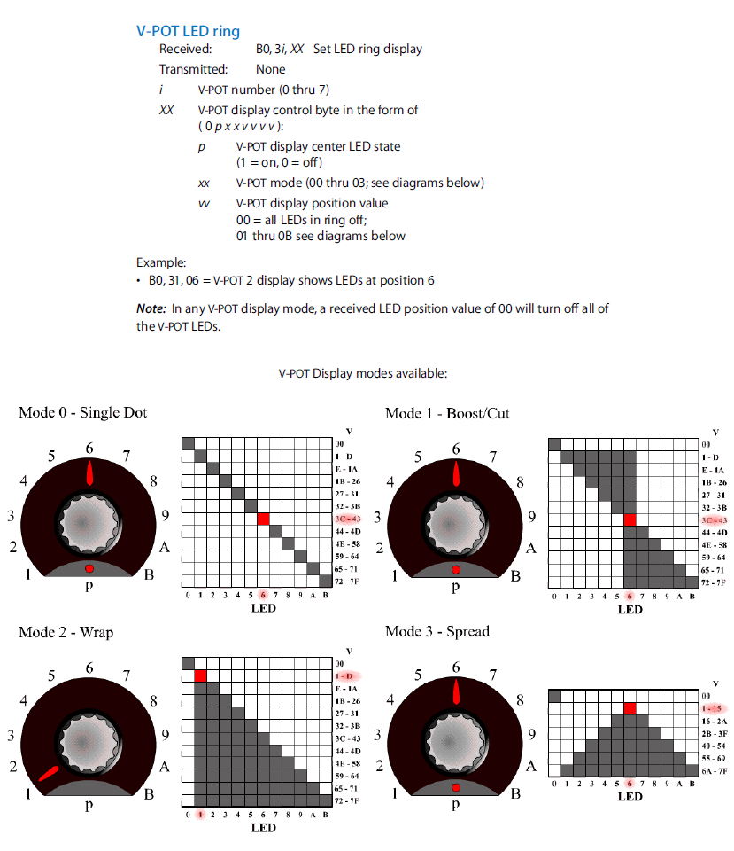
This is not wrong in midi-terms, but in all honesty i will ask you know, what did you understand better. My example or theirs… ![]()
![]()
![]()
More updates for the documentation of this Mackie C4 project are coming soon in this thread.
Mackie C4 remote panel for Novation A-Station v01…bmtp (60.8 KB)
Mackie C4 remote panel for Novation A-Station v03…bmtp (106.2 KB)

A-Station.pdf (1.6 MB)