I’m new to the MIDI world.
I understand the basics.
Now to my problem.
I have a Behringer X-Touch (Full) and would like to use it to control the Daslight software.
I’ve already managed to use the faders including feedback with the BMT Pro.
Now, depending on the brightness of the lamp I am controlling, I would like to use the Behringer’s VU meter to display the brightness.
However, I’m currently failing to understand how the MIDI message is put together.
There is an example of the V-Pod LEDs in the instructions.
However, I don’t understand how I can get the 2 values (06) from the 8 (0pxxvvvv) values in the example
I did some other bit manipulation to handle the VPOT ring type and VPOT number. Here are the rules that I used with comments included.
// set mode
// 0, 1 , 2 or 3
oo=0
// scale value
// output range 0-11 or 12
qq=qq*12
// input ranges 0-127 or 128
qq=qq/128

Log "Log value on output is %qq%"
// shift mode bits into position
oo=oo<<4
// OR it with value to get resulting output value
qq=qq|oo
// which vpot number 0-7
rr=0
// add vpot number to message
tt=rr|48
I’m just trying to understand how the message in the instructions is put together.
B0, 31, 06
B0, 31, is clear.
However, the 06 in the example should be put together
0pxxvvvv
I understand what is meant by p, x and v.
I understand that this 06 in the example comes from the 8byte? (0pxxvvvv) is put together.
According to the example, these 8 bytes should then be (00003c43), right.
Is it 8 bytes?
Then what are the 06?
And how do I get to this result?
0pxxvvvv is 8 bits
0 is the bit 7
p is bit 6
xx is bits 5 and 4
vvvv is bits 3-0
You have 3 bytes. Each byte has 8 bits
B0 is the first byte 1011 0000 (binary)
3x is the second byte where x is the VPOT Number
example 31 = 0011 0001 binary
06 is the third byte 0000 0110 (binary)
Binary to Hex
0000 = 0
0001 = 1
0010 = 2
0011 = 3
0100 = 4
0101 = 5
0110 = 6
0111 = 7
1000 = 8
1001 = 9
1010 = A (10 decimal)
1011 = B (11 decimal)
1100 = C (12 decimal)
1101 = D (13 decimal)
1110 = E (14 decimal)
1111 = F (15 decimal
So you have 3 bytes, each byte is 8 bits
I use bit shifting to fill the bits in the right location (see rules) and the manual for what bit shifting is. You can press F1 to read the Bome MIDI Translator Pro manual.
If you want to see it in action, turn on the log window and you if you check ‘rules’ you can see what the rules are doing. If you check MIDI out, you can see the output that is generated.
Steve Caldwell
Bome Customer Care
Also available for paid consulting services: bome@sniz.biz
Thanks a lot.
I want to learn by testing.
Your answer helps me a lot.
I would now like to use the level meter LEDs of the x-touch to show me what the DMX value in my lighting software Daslight is, i.e. how bright a lamp is at the moment.
With your information I can now understand the instructions better and will try my luck.
Could you give me an example of how to convert variable bite into a hex value in a rule. e.g.: xx = (0hhhiiii) 0hhh is 0-7 - is fixed iiii is 0-127 - is variable how do I get the rule for this 0hhh (0111) and the variable iiii (0-127) to a HEX value. I then need B0 xx as an output
Byte 1 - The control Byte is 8 bits B0 Hex is 1011 0000
Byte 2 and 3 - will each require 7 bits
A value of 0-127 requires 7 bits so for the 3rd byte the Mackie MCU only uses 4 bits for the LED value, 2 bits is to tell it the LED type and 1 bit for center LED state.
For scaling 0-127 to be 0-11, I used the following to get the last 4 bits. This tutorial discusses scaling.
qq=qq*12
qq=qq/128
Now qq should contain a number between 0 and 12
For the othert 3 bits I just created the value I want and shifted it 4 bits to the left
tt=1<<4
Then you OR these bits with qq to get the final result
qq=qq|tt
Now qq should contain the bits you want
This was all shown in the rules of my previous project example, although I may have used different variables.
You can also look at this post for information on bit mapping.
Steve Caldwell
Bome Customer Care
Also available for paid consulting services: bome@sniz.biz
Unfortunately, the level meters of the X-Touch only show the peak and immediately fall back to zero.
I have now solved this so that the current values are saved in a global variable and are output again and again using a 100 ms timer.
Definitely not the prettiest solution, but it works.
Do you still have an option to use the LCD displays?
All the options I have found so far have not been successful.
I tried different headers but unfortunately nothing appeared on the display.
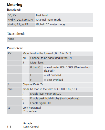
This is strange. You are using the VPOT rings as level meters, correct? I would like to look at your solution to see why you have to keep sending the same values over and over again. Could you post the project file? If you are actually using the Meter instead, it requires a different MIDI signal as described on page 118 of the document you sent me. I can’t test this because I don’t have a unit that has meters.
Although I do not have a unit with meters. The following should take CC0-CC7 and convert there values for each of your channel meters. Translator 0.1 does this and the other translators are disabled.
0.0 will take CC0-CC7 and convert to VPOT rings
0.2 will take an actual Meter signal from the DAW and convert it to VPOT rings
Hi,
The main thing I see is that you need to set up your routing correctly. There were several places where you were routing all MIDI messages to everything which is generally not a good idea.
For more information about routing/evice selection, see this tutorial.
Then you need to set up and use only aliases, if you send something to a hardware port and also to the alias that points to the same hardware port, it will be sent twice.
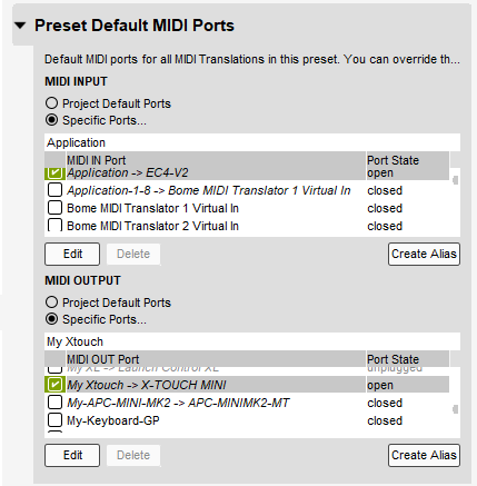
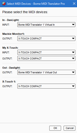
I set up the aliases as follows on my machine and have ensure MIDI message only go to the desired aliases.
You can learn more about aliases from this tutorial.
Also , I modified your LCD MIDI message for standard Mackie format that should work. I don’t have an X-touch to test the custom X-Touch Scribble strip messages.
It is possible that you had the routing wrong.
Finally, I added a Meter Preset (4), it should take CC0-CC7 on MIDI Channel 1 and send the level to your meters. CC10 will co to CH1 meter and CC17 to CH8 Meter. Again, I cannot test this so am just going by the documentation. I also set up a Channel meter mode message on timer ‘Init’ but the document was not very clear on this so I can’t test it either.
I tried the alias thing, but somehow made a mistake. I’ll watch the tutorial.
I’ll take a look at your file tomorrow, thank you very much.
to the mode of the x-touch.
I tested everything with my message.
I’ll take a look with her too.
The x-touch has the modes MC, HUI, Ctrl, CtrlRel, and various Xctl.
I think that the Ctrl is the MIDI mode.
Yes, probably Ctrl mode for special scribble strips but it will break everything else so I would recommend sending Mackie MCU standard format and use Mackie MCU mode.
Steve Caldwell
Bome Customer Care
Also available for paid consulting services: bome@sniz.biz
So the LCD described works.
a bit strange but it works.
it takes all 8 LCDs as one. This means that if you only want the third letter, you have to insert 16 blank spaces or move the first character with the HEX value in front of the text.
It’s ok for me now, since I’ve written it once and that’s it.
the level meters work as I described.
they take the current value, display it briefly and drop back to zero.
then I will do this via global variables that are output every 100ms.
or could that lead to problems if the signals are output so often?
Is it possible to send several commands at the same time via a translator.
Then a translator would be enough for the 8 level meters, or do I need a separate one for each level meter.
Hi,
In the below example I have 2 examples of using timers.
5.4 does a single meter on each pass and requires a more frequent timer. I have left this disabled.
5.5 does an 8 meter pass on each iteration so requires a less frequent timer. This one I have enabled.
I also changed the range of the meters so that the red LED flows. I set up a preset and translator to initialize any global variables I need. I usually do this for my projects to keep my global variables tracked and in one place. This is done under preset 0 (Init) translator 0.2.
If I could figure a way to keep them lit any other way, I would but I wasn’t able to figure it out. I found an X-touch One that I used for testing since it had a meter.