Bome Networks - Routing Basics

I have set up Bome Network with Unlimited Named MIDI Ports, but I am a bit confused about how basic routing works.

Is there documentation on this? I’ve looked (moderately hard) but can only find stuff related to BomeBox. If there is documentation, I’d love a pointer. If not …

One of the basic need is to connect an EC4 to both Cantabile and (occasionally) to the browser-based editor. Based on This Post, I’ve sketched out a setup like this:

The circled numbers follow the number in This Same Post mentioned earlier.

However, I cannot see how to connect In to In in the Bome Network Interface … e.g. MIDI routes marked (1) in the above diagram. The only routes that seem to be allowed are In to Out.

Also …

In a more general sense, I’m finding this setup rather mind-bending. Was it done with as few ports as possible for efficiency? Would there be a downside to adding a few more Unlimited Named MIDI Ports with a few extra MIDI hops - is there a performance hit for additional hops??

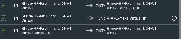
In order to route in to in our out to out you need to turn Advanced MIDI Router in the Setting (Cog Icon)
image

I just did it the way it made sense to me. The more virtual ports you add, the more routes you need to have, so I only created two.

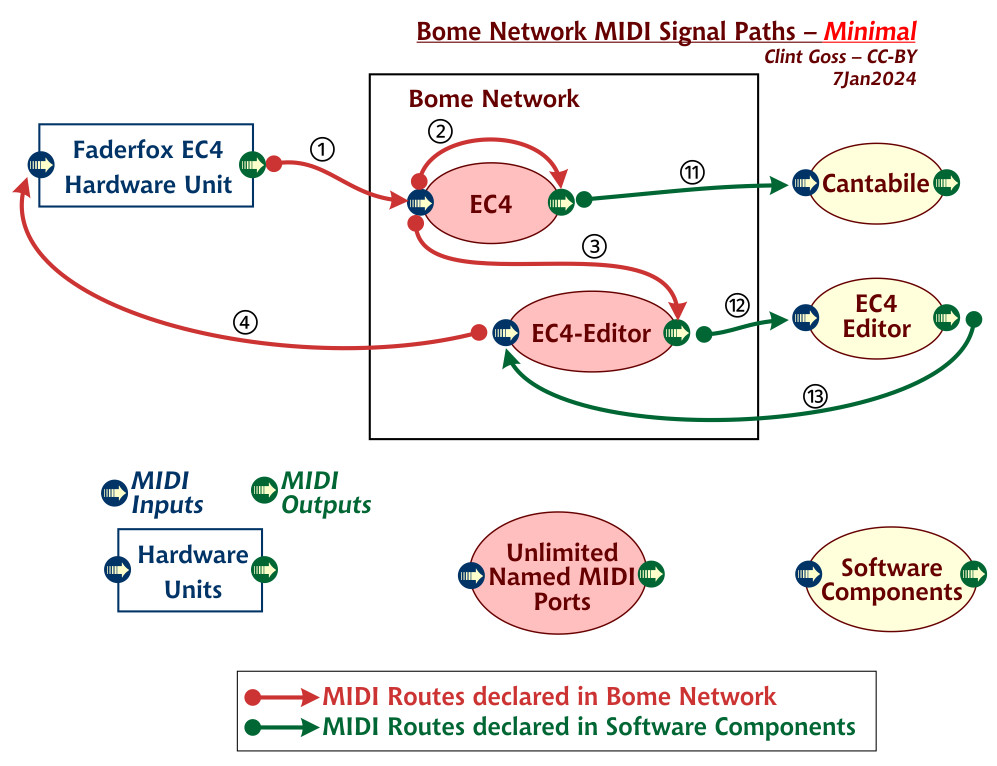
Here is a writeup I did when analyzing Bome Network before it was released. I periodically refer to it to keep my head on straight. I’m not sure if it is 100% accurate but for now this is what I use unless something trips me up.


Bome Unlimited Virtual MIDI ports are really just connectors or endpoints. Without routing, they actually do nothing as they are connectors to ‘nowhere’.

You need to use the Bome Network Router to make them actually useful by creating MIDI routes between the connectors and put real devices or applications on one end of a given connector.

The below is a summary of my discovery while experimenting with them:


INPUT to OUTPUT

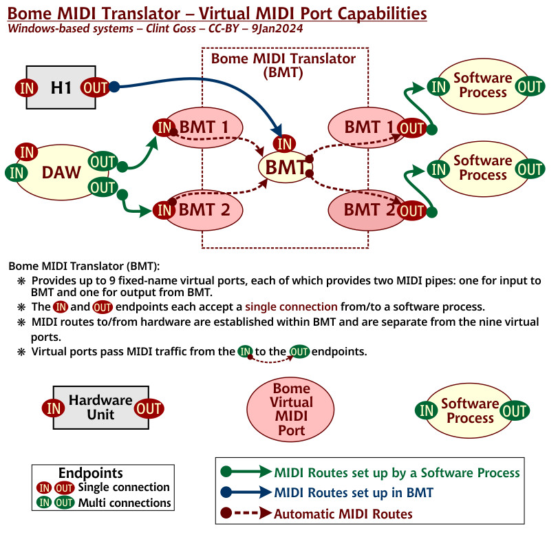
When you create a Bome Virtual MIDI point you create two endpoints. One for INPUT and one for OUTPUT.
You can route the input of one port to the output of the same port to create a one way pipe. For instance if you have INPUT ‘A’ routed to OUTPUT ‘A’. Then with your application you can send MIDI to INPUT ‘A’ and whatever you send there will be also seen on OUTPUT ‘A’.

You can also direct two inputs to a single output with 2 routes. For instance if you have INPUT ‘A’ routed to OUTPUT ‘A’ and OUTPUT ‘B’, whatever MIDI comes in to INPUT ‘A’ will be seen on both OUTPUT ‘A’ and OUTPUT ‘B’.


INPUT to INPUT

Another thing you can do is direct an INPUT to another INPUT. This could be handy if you want to inject an input from one input port to another. You can then route the initial destination ports to other ports, creating a MIDI split function that can quickly be turned on and off with by checking or un-checking a given routing.

Example:
Route 1 - IN: A Virtual In ->IN: B Virtual In
Route 2 - IN: B Virtual In → OUT: C Virtual Out
Route 3 - IN: B Virtual In → OUT: D Virtual out

In the above, anything coming into either A or B will be sent to C and D. However, you could turn off Route 1 and then only B will be sent to C and D. A will essentially be turned off allowing only B to be split to C and D.
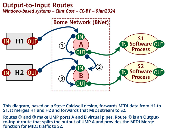

OUTPUT to INPUT
This is used for injecting an existing output port’s data into a different input connector (virtual ports only). You can take the output of one port and direct it to the input of another port.

Example
Route 1 - IN: A Virtual In → OUT: A Virtual Out - MIDI pipe as explained earlier
Route 2 - OUT: A Virtual Out → IN: B Virtual In
Route 3 - IN: B Virtual In - > OUT: B Virtual Out - MIDI pipe as explained earlier

Anything coming from input A will go to output A and input B which in turn will go to Output B. Anything coming from input B will only go to output B. Essentially we get a split on input from A (to A and B) and a pipe from B (B to B)

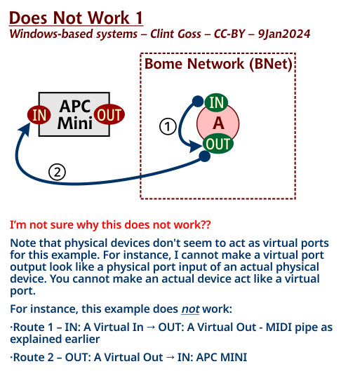
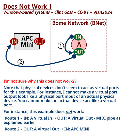
Note, that physical devices don’t seem to act as virtual ports for this example. For instance I cannot make a virtual port output look like a physical port input of an actual physical device. You cannot make actual device act like a virtual port.

For instance, the below example does not work:

Route 1 - IN: A Virtual In → OUT: A Virtual Out - MIDI pipe as explained earlier
Route 2 - OUT: A Virtual Out → IN: APC MINI

Rather you should do this:

Route 1 - IN: A Virtual In → OUT: A Virtual Out - MIDI pipe as explained earlier
Route 2 - OUT: A Virtual Out → IN: Virtual APC MINI
Route 3 - IN: Virtual APC MINI → OUT: Virtual APC MINI - MIDI pipe as explained earlier
Route 4 … - IN: Virtual APC MINI → OUT: (Any other destination)

Or you could do this to achieve the same result (but not represented as output to input) See OUTPUT to OUTPUT Below:

Route 1 - IN: A Virtual In → OUT: A Virtual Out - MIDI pipe as explained earlier
Route 2 - OUT: A Virtual Out → OUT Virtual APC MINI
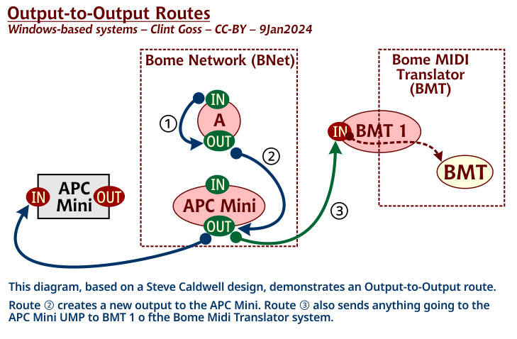

OUTPUT to OUTPUT

You can duplicate output ports in this configuration essentially providing a MIDI split function

Example
Route 1 - IN: A Virtual In → OUT: A Virtual Out - MIDI pipe as explained earlier
Route 2 - OUT: A Virtual Out → OUT: APC MINI
Route 3 - OUT: APC MINI → OUT: BMT 1

Route 2 above creates a new output to my attached APC MINI device. Everything coming in Virtual Port A (which is a Pipe to Virtual Port A Output) will go to my APC MINI

Route 3 will also send anything that is going to the APC MINI to BMT 1 Output

In summary:
When the source is input and destination is output you create a 1 way pipe
When destination is input you are injecting the MIDI data from the source (input or output) to the endpoint. This appears to only work with Virtual MIDI ports if you are injecting to a destination input.
When the source and destination are outputs you are essentially duplicating existing ports to allow for a MIDI split function.
It appears that the quickest way to get a MIDI merge function is to take multiple existing INPUTS as a source and route to a single OUTPUT as a destination.

NOTE: This all appears NOT to work correctly with BMT Ports if used with Bome MIDI Translator PRO since BMT ports cannot be routed between themselves and one and only one end of a BMT port connection must be MT Pro while the other end must not.

Also virtual MIDI ports generated by other applications such as LoopMIDI or LoopBE may behave different as most appear to be MIDI pipes.

There are limitations when including physical ports into the mix as described above. Best to create virtual port connections with the physical ports and use applications with the virtual port connectors only. Attempting to inject into a physical port input does not seem to work, although routing signal to output does.

Steve Caldwell
Bome Customer Care


Also available for paid consulting services: bome@sniz.biz
1 Like

Oh and also I was successful with the Pacer Editor as in the other post but I had trouble with the EC4 editor. I haven’t figured out why yet. I just disable the routes and went direct to and from my EC4 from the FaderFox EC4 editor tool. I also had to allow MIDI on their site to get it to work. Hopefully you already downloaded and installed the new V2 stuff. The only issue I ran across is I had to reprogram all of my note push messages as they are new and the old ones just defaulted to momentary note of on whatever MIDI CH and CC number the knob had.

Steve Caldwell
Bome Customer Care


Also available for paid consulting services: bome@sniz.biz
1 Like

Guess I’ve jumped into the Big-Boy end of the pool. Treading water fast and have one nostril above the water line …

Thanks for this extensive info …

I am still on v1.01 of EC4 firmware and the editor. Upgrading now. Offline editor does not perform a firmware upgrade, but the public version at Faderfox EC4 Editor (FW 2.x) does the upgrade to v2.00. I reported the issue on GitHub.

The Type of each Push action needs to be converted from a [blank] setting to [Note] for each of my 16 Groups in each of the 16 Setups. Ugh. Thankfully this can done for all encoders in a Group at once using the editor’s [Copy ‘Type’ to all encoders in Group] function in the editor.

What is more challenging, for those of us that made extensive use of sending [Note On/Off] commands (in 100+ Groups), is the programming of the Chan and Numb settings in each knob in each Group.

Diagrams are sorely needed (by me, at least) for the MIDI routing scenarios you describe … will see what I can cook up …

Yep, straight into the deep end. My write-up was with a few days playing around. It took me a while to get it and sometimes I still struggle. With power comes requirement for knowledge.

For the push actions, I end up just setting the up directly on the controller as I need them since there are a total possibility of 16 buttons x 16 setups x 16 groups or 4096 button choices. I think I have only 1x16x4 or 1024 buttons programmed right now. (4 groups and one setup)

I could spend more time on it but I’m really not using that much. I guess it would be nice if he would have set some kind of default with V.2 but it probably would have overwritten all of the other programming that was already done.

As far as diagrams, I agree. The setup interface although powerful, doesn’t usually give me the visual I need. If you could create a picture of what you want (similar to what you or I did), and send it to the application for implementation that would be nice but I think that would be a huge undertaking.

Another tip. When you have the routes that you want working, make a backup of the settings. They are kept in

%APPDATA%\Bome

and the settings file is called
BomeNet.bmts

Although there a backup files periodically generated, I also make copies of my own with a date stamp like.

BomeNet-2024-07-08.bmts

That way if my settings file gets hosed, I can always go back to a working version by simply renaming it BomeNet.bmts (while Bome Network is not running). Then restart Bome Network.

Steve Caldwell
Bome Customer Care


Also available for paid consulting services: bome@sniz.biz

I’ve worked through the various Virtual MIDI Ports options and your scenarios as best I can and done some diagrams … Any and all thoughts welcome!

First, some details on how I think LoopMIDI and LoopBe work:

I did some testing in LoopMIDI, and was able to connect multiple software processes (BMT and MidiView) to a LoopMIDI output port, so those ports do seem to allow multiple connections.

And here is my understanding of the way BMT works:

… and now for the Unlimited Named MIDI Ports (I call them UMPs) of Bome Network (which I call BNet). This comes from your Pacer example:

Here’s is the first scenario in your writeup, which seems straightforward …

I was thinking that it would be simpler to treat B as a Pipe (with a single route) and connect both S1 and S2 to the Output of B … except that the connection is done from S1 and S2 and they cannot both connect to the same MIDI port under Windows.

Here is your Output-to-Input Route Example:

And then I kind of lost it … I may be confused between the APC Mini Virtual Port in BNet and the APC Mini hardware:

And I’m not sure why this is needed …

… and finally … I’m really not sure if this is correct … Configuring the APC Mini to connect as well as BMT 1?? Seems like a Windows conflict …

Nice diagrams!

I’ll have to ponder on a few things a bit more. It seems that when you are sending things over Bome Network, that routing is a little different than a locally attached MIDI port.

I’ll have to play with it a bit more. It seems that the INs and OUTs are a bit different over the network.

I see you had some success with LoopMIDI which I really did not dig into too much as my evaluation was based mostly on Bome Products, Software Products (like DAWs) and MIDI hardware.

Steve Caldwell
Bome Customer Care


Also available for paid consulting services: bome@sniz.biz

On out to in, my point is you cannot direct a Virtual Out to a Hardware In. Instead you have to create a Virtual In for the hardware and create a pipe and use that instead of the original hardware port in MT Pro.
Then you can direct other Out (from other ports) to the IN of the newly created Virtual port to make the out of the virtual port look like the input came from the same virtual In. It is really a kind of MIDI merge.

Route1 - IN: A → OUT:A
Route2 - IN: APC-MINI → IN: V-APC-MINI
Route3 -IN: V_APC-MINI → OUT: V-APC-MINI
Route4 -OUT: A ->IN: V-APC-MINI

If you are sending anything to A then it will look to the application (i.e. MTPRO) that it can from V-APC-MINI
I’m not sure how useful this is as you could do the same thing with a merge function. I just wanted the scenarios to show all possible combinations. There might be other applications for this scenario, but I really can’t think of one.

Also note that if you are using Remote Direct MIDI, then Bome Networks makes additional endpoints automatically from the remote port and automatically creates some routes. You can disable these routes if you want.

For instance see below where I have FaderFox UC4 remotely connected (through a virtual port on the remote machine). The lines without the ‘i’ are created by Bome Network when you use Remote Direct MIDI. The one in the middle I created to force the RDM port to behave like it is coming from the locally created Virtual Port. This way if my demographics of remote ports change, I can just change the route in Bome Network instead of in a given application on the local machine.

image

Steve Caldwell
Bome Customer Care


Also available for paid consulting services: bome@sniz.biz
1 Like

RIGHT! Remote MIDI … not up to that grade yet. Still swimmin’ in the pool (deep end) but not yet the ocean. I doubt at this point whether I’ll be using a real network for MIDI … but maybe down the line …

So the exercise of creating the diagrams helped me for ports and routes in Bome Network … I just didn’t get how they worked with the routes spelled out in text. Hope the diagrams may be useful to others …

I’m sure your diagrams will prove quite useful. That was the primary reason I created one for my Pacer config because without a picture, I had a hard time keeping my routes straight. Generally when I create a complex set of routes, I will sketch it out on paper as a picture first. Your diagrams are much prettier than mine

Steve

Explanation of the following

The APC MINI Input is actually what you would see with something coming IN from the APC MINI. If you want to send something to the APC MINI you would send to it’s Output.

Now if you wanted to make your computer think it was getting something from the APC MINI but it was actually coming from A, then a 3rd route would be to connect.

IN: APC MINI → OUT: Destination device

Anything sent from A in the diagram above would be seen on the Destination device and it would think it came from the APC MINI.

I hope this clears things up.

Steve Caldwell
Bome Customer Care


Also available for paid consulting services: bome@sniz.biz
1 Like